Send Message
Home
Products
About Us
Factory Tour
Quality Control
Contact Us
Request A Quote
Home ProductsCircuit Board Wire Connectors

1.00mm Pitch Circuit Board Wire Connectors Crimp Housing Single Row 6 Position

1.00mm Pitch Circuit Board Wire Connectors Crimp Housing Single Row 6 Position

    • 1.00mm Pitch Circuit Board Wire Connectors Crimp Housing Single Row 6 Position
    • 1.00mm Pitch Circuit Board Wire Connectors Crimp Housing Single Row 6 Position
    • 1.00mm Pitch Circuit Board Wire Connectors Crimp Housing Single Row 6 Position
  • 1.00mm Pitch Circuit Board Wire Connectors Crimp Housing Single Row 6 Position

    Product Details:

    Place of Origin: Dongguan, China(mainland)
    Brand Name: HRT
    Certification: ISO9001/ ISO14001/UL/RoHS/REACH
    Model Number: A1016H-06P

    Payment & Shipping Terms:

    Minimum Order Quantity: 5000 pcs
    Price: Negotated
    Packaging Details: Bag with outside carton
    Delivery Time: 5 to 8 working days after payment checked
    Payment Terms: TT, Western Union, PayPal, L/C
    Supply Ability: 28 million pcs per month
    Contact Now
    Detailed Product Description
    Color: Light-yellow Pitch: 1.00mm
    Material: LCP Wire Range: AWG30# To 32#
    Flammability: UL94V-0 Row: Single
    High Light:

    Printed Circuit Board Connectors

    ,

    Pcb Connectors Wire To Board

    ,

    LCP Material Circuit Board Wire Connectors


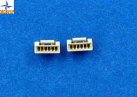
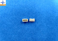
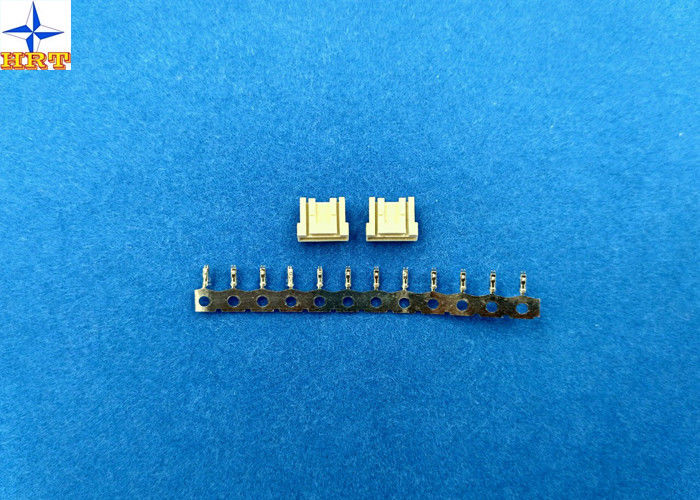
    1.00mm Pitch Circuit Board Wire Connectors Crimp Housing Single Row 6 position


    1, The detailed specification excel


     Basic size information
    Category Crimp housings
    Suitable terminals A1007T series
    Lock to mating part With
    Panel mount No
    Circuits 6 pins
    Wire insulation diameter  0.80mm Max.
    Terminal material phosphor bronze
    Terminal finish tin-plated or gold-flash
     
                                                Electrical properties
    Current Rating 1A AC, DC
    Voltage Rating 60V AC, DC
    Contact Resistance 20mΩ Max
    Insulation Resistance 100mΩ min
    Withstanding Voltage 600V AC/minute
     
                                                    Mechanical properties
    Temperature range -25℃ to 85 ℃
     
              Other information please kindly check the following picture.


    2, Related drawing and report

    Folllowing pictures are out testing report and exact engineering drawing for your information, please kindly check it, wish it can help you to get what you really need.

    1.00mm Pitch Circuit Board Wire Connectors Crimp Housing Single Row 6 Position

    1.00mm Pitch Circuit Board Wire Connectors Crimp Housing Single Row 6 Position

    1.00mm Pitch Circuit Board Wire Connectors Crimp Housing Single Row 6 Position

     
    5. Mechanical Performance


    Test Description Procedure Requirement
    5-1 Actuator Insertion & Withdrawal Force Insert and withdraw connectors at the speed rate of 25±3mm / minute. Refer to paragraph 7
    5-2 Crimping Pull Out Force Fix the crimped terminal, apply axial pull out force on the wire at the speed rat of 25±3mm / minute.(Based upon JIS C5402 6.8) AWG#30 1.0kgf (Min)
    AWG#32 1.0kgf (Min)
    5-3 Terminal Insertion Force. Insert the crimped terminal into the housing. 0.80kgf (Max.)
    5-4 Terminal/Housing Retention Force. Apply axial pull out force at the speed rate of 25±3mm / minute on the terminal assembled in the housing. 0.80kgf (Min.)
    5-5 Pin Retention Force Apply axial push force at the speed rate of 25±3mm / minute 0.50kgf (Min.)
    5-6

    Locking Strength

    (Housing)

    Mate the connectors and apply the force by pulling axially the housing at a rate of 25 ± 6 mm per minute. Strength is determined when locking device disengaged locking, or is broken by the load. 1.50kgf (Min.)
    5-7 Durability When mated up to 30 cycles repeatedly by the rate of 10 cycle per minute. Contact Resistance 20mΩ (Max.)
    5-8 Vibration

    Amplitude: 1.5mm P-P

    Sweep time: 10-55-10 Hz in 1 minute Duration: 2 hours in each X.Y.Z. axes.

    (Based upon MIL-STD-202 Method 201A)

    Appearance No Damage.

    Contact Resistance 20mΩ (Max.)

    Discontinuity 1 μsec.(Max.)

    5-9 Physical Shock 490m/s²{50G},3 strokes in each X.Y.Z. axes. (Based upon JIS C0041/MIL-STD-202 Method 213B Cond. A)


    6. Environmental Performance And Others


    Test Description Procedure Requirement
    6-1 Temperature Rise Carrying rated current load.(Based upon UL 498) 30℃(Max.)
    6-2 Heat Resistance 105±2℃,96 hours (Based upon JIS C0021/MIL-STD-202 Method 108A Cond. A)

    Appearance No Damage.

    Contact Resistance 20mΩ (Max.)

    6-3 Cold Resistance -40±3℃,96 hours (Based upon JIS C0020)
    6-4 Humidity

    Temperature: 60±2℃

    Relative Humidity : 90~95%

    Duration: 96 hours

    (Based upon JIS C0022/MIL-STD-202 Method 103B Cond. B)

    Appearance No Damage.

    Contact Resistance 40mΩ (Max.)

    Insulation Resistance 100MΩ (Min.)

    Dielectric Withstanding Voltage Must meet 4-3

    6-5 Temperature Cycling

    5 cycles of:

    a) -40℃ 30 minutes

    b) +105℃ 30 minutes

    (Based upon JIS C0025)

    Appearance No Damage.

    Contact Resistance 20mΩ (Max.)

    6-6 Salt Spray Tin-plated 24 hours / Gold- plated 48 hours exposure to a salt spray from the 5±1% solution at 35±2℃. (Based upon JIS C0023/MIL-STD-202 Method 101C Cond. B)
    6-7 SO2 Gas

    24 hours exposure to 50±5ppm.

    SO2 gas at 40±2℃.

    6-8 NH3 Gas 40 minutes exposure to NH3 gas evaporating from 28% Ammonia solution.
    6-9 Solderability

    Soldering Time: 5±0.5 sec.

    Solder Temperature: 245±5℃

    Solder Wetting 95% of immersed area must show no voids, pin holes
    6-10 Resistance to Soldering Heat

    When reflowing

    Refer to paragraph 8

    Solder iron method

    Soldering Time: 5±0.5 sec.

    Solder Temperature: 370℃ ~ 400℃

    Appearance No Damage.

    7. Actuator Insertion/Withdrawal Force

    [Unit : kgf]

    Circuits At Initial
    Insertion (Max.) Withdrawal 1st (Min.) Insertion 6th (Max.) Withdrawal 30th (Min.)
    Single 1.5 0.03 0.03 0.03
    02 1.7 0.06 0.06 0.06
    03 1.9 0.07 0.07 0.07
    04 2.0 0.08 0.08 0.08
    05 2.2 0.09 0.09 0.09
    06 2.3 0.12 0.12 0.12

    8. Applicable Wires:

    AWG Size: AWG#30 UL1571 Insulation OD: Φ0.70mm

    AWG#32 UL10064 Insulation OD: Φ0.42mm

    9. Crimping Condition

    Wire Specification Crimp Height(mm) Crimp Width(mm)
    UL AWG OD A B W1 W2
    UL1571 #30 0.70 0.51-0.54 0.65-0.70 0.70-0.75 0.80 MAX.
    UL10064 #32 0.42 0.48-0.52 0.60-0.65 0.70-0.75 0.80 MAX.


    3, Applicated field of this product by graphical representation

    This product is widely used in computer, household appliance and so on. You can get this message through the pictures.


    1.00mm Pitch Circuit Board Wire Connectors Crimp Housing Single Row 6 Position

    Contact Details
    RULETEAM CONNECTION TECHNOLOGY (SHENZHEN) CO.,LTD

    Contact Person: Tienne Chen

    Tel: +8613711905178

    Send your inquiry directly to us (0 / 3000)

    Other Products